
Measure conveyor discharge height and the receiving surface from a shared site datum, then record the opening, horizontal gap, overlap and approach angle. Check the proposed arrangement across its intended adjustment positions. Final dimensions belong in the line layout, while a controlled potato trial establishes whether the transfer enters cleanly, avoids accumulation and meets agreed acceptance criteria.
Key takeaways
- Use one site datum and identify each height reference surface.
- Measure opening, angle and overlap alongside discharge height.
- Check geometry and access across every intended adjustment position.
- Accept the connection through a documented trial with representative potatoes.
Why matching outlet height can still leave a poor transfer
The practical problem is a conveyor that fits the building and reaches the requested height but sends potatoes into a receiving lip, leaves an excessive drop or crowds the receiving opening. An outlet elevation alone cannot describe that connection. The delivery direction, horizontal separation, receiving surface and crop stream width all influence where potatoes land. We therefore treat discharge height as one coordinate within a complete interface survey.
Define the operating arrangement before taking measurements: where the receiving equipment stands, which direction it accepts material and whether either interface changes position during use. Record the intended hourly flow and representative potato size range alongside the geometry. These inputs connect the physical survey to the operating problem. A layout that works for a sparse stream may behave differently when the receiving area carries a deeper bed or an uneven feed.
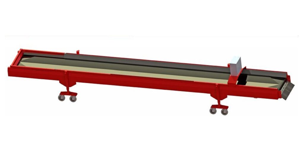
Survey the opening, approach angle and overlap together
Measure the clear receiving opening at the point where potatoes enter, including any narrowing caused by side walls or protruding edges. Record its centreline relative to the conveyor centreline and its orientation in plan. An opening can be wider than the belt yet still intercept the crop stream when the conveyor approaches at an angle. Include a side elevation showing the discharge edge, receiving lip and downstream surface.
Define overlap explicitly on the drawing as the horizontal position of the discharge edge relative to the receiving edge. Too little reach can leave an exposed gap; excessive reach can place the outlet inside a restricted space. Belt speed and approach slope also influence the departure path, so a static drawing cannot establish the landing position by itself. The guide to gentle potato handling and conveyor design provides complementary context for evaluating the transfer.
Choose the conveying role before fixing the connection
The BSSJ8-08 potato conveyor provides adjustable height and speed for conveying between cleaning, grading, storage and packing equipment. The BSS16-08 double layer conveyor provides adjustable belt speed and height for long-distance warehouse transfer. Compare their published inlet, outlet and overall dimensions with the surveyed connection. A height range is a selection input; the final arrangement still needs a drawing that defines the actual interface position.
The potato roller lifter uses stainless rollers to rotate and elevate potatoes in a single layer, helping maintain a stable feed to the sorting machine. Consider this role when the receiving process requires that presentation. Its dimensions and installation clearances are confirmed with the line layout. Do not assume its elevation range or footprint from another conveyor, or treat the three equipment roles as geometrically interchangeable.
| Equipment | Published dimensions | Stated function or adjustment | Meaning for the survey |
|---|---|---|---|
| BSSJ8-08 | 8050 × 1300 × 1300 mm; belt width 800 mm; inlet height 800 mm; outlet height 490-890 mm | Height and speed can be adjusted; conveying between cleaning, grading, storage and packing equipment. | Compare the stated inlet and outlet heights with the surveyed interfaces. |
| BSS16-08 | Length 9000-15850 mm × width 1820 mm × height 1710 mm; belt width 800 mm; inlet height 850-1150 mm; outlet height 900-1450 mm | Belt speed and height are adjustable for long-distance warehouse transfer. | Review the selected length and both interface heights together. |
| Roller lifter | Dimensions and installation clearances are confirmed with the line layout. | Stainless rollers rotate and elevate potatoes in a single layer, helping maintain a stable feed to the sorting machine. | Establish its interface geometry in the proposed line layout. |
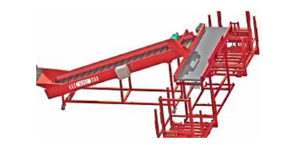
Check the complete adjustment envelope and access
Show the proposed operating position and every intended adjustment position on the layout. Changing the height of an inclined conveying path can change its approach angle and the horizontal location of its outlet. Determine those movements from the proposed arrangement rather than assuming purely vertical travel. For equipment with a published length range, confirm the selected length together with inlet height, outlet height and the space available around the receiving interface.
Reserve access for adjustment, inspection and the maintenance tasks required by the final equipment arrangement. Include nearby columns, doors, platforms and routes used to remove components. Any added chute or transition should have defined attachment points and a removal route. Our potato handling line solutions can be discussed around these site constraints. Clearance dimensions belong in the project layout; the available product information does not establish universal access distances.
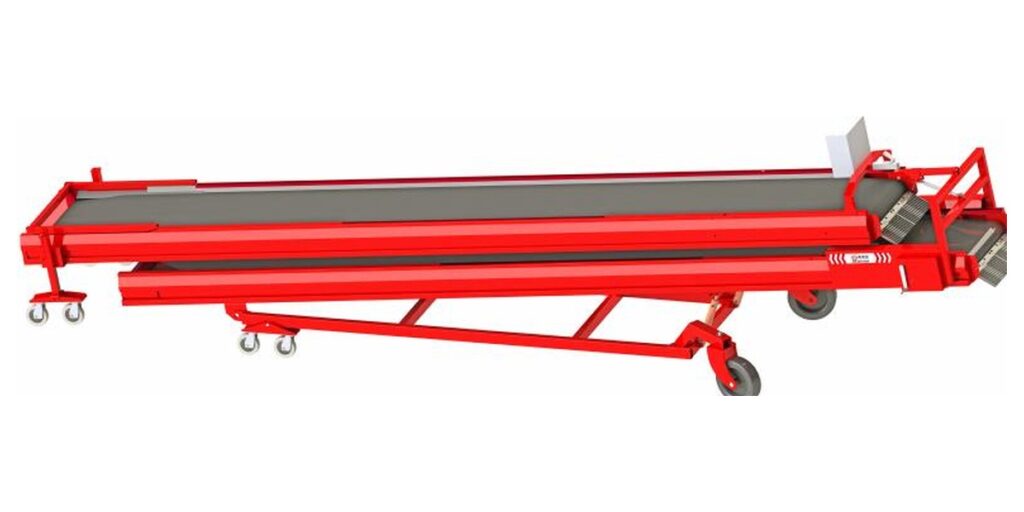
Use the crop path to explain transfer problems
After potatoes leave a conveying surface, their motion depends on departure speed, direction and gravity until they contact the receiving equipment or other potatoes. A higher outlet can increase the available fall, while a different belt speed can shift the landing position. The receiving bed changes the effective landing surface as material accumulates. This explains why raising the outlet alone may move a problem without resolving the underlying mismatch.
For a hypothetical transfer where potatoes strike the front lip, inspect outlet position, approach angle and landing path before changing speed. If potatoes enter successfully but accumulate downstream, examine the receiving process and feed consistency before changing the gap. Change one variable at a time and record its effect. Visible bouncing, rolling back or edge contact identifies conditions to investigate, but observation alone does not quantify crop damage or establish an acceptable operating limit.
Accept the interface with a controlled crop trial
First compare the installed interface with the agreed drawing, including datum elevations, opening dimensions, centreline alignment and adjustment positions. Check movement through the intended range without material under the site’s commissioning procedure. Then introduce representative potatoes at a controlled feed rate and observe entry, landing and evacuation from the receiving area. Increase toward the required operating condition only after the preceding condition has been assessed and recorded.
A successful trial supports the tested crop and operating conditions. It does not establish performance for every size distribution, surface condition, feed fluctuation or receiving arrangement. A conveyor’s approximate published capacity also does not demonstrate the capacity of the complete transfer. When the crop, receiving equipment or installation position changes, review the affected dimensions and repeat the relevant acceptance observations. Use the survey and trial requirements together to define a project-specific connection.
| Trial observation | Geometry or flow to inspect | Controlled follow-up | Acceptance evidence |
|---|---|---|---|
| Potatoes strike the receiving lip | Lip elevation, discharge position and approach angle | Adjust one permitted setting and observe the landing path again. | Recorded entry path at the agreed operating condition. |
| Material spills along one side | Centreline offset, opening orientation and stream width | Check alignment before changing feed or speed. | Observation of both opening edges during the trial. |
| Material builds up after entering | Receiving evacuation and incoming feed consistency | Reduce feed to establish whether accumulation clears, then retest. | Recorded feed rate and accumulation behaviour over the agreed duration. |
| Transfer works only at one height | Outlet movement, overlap and surrounding restrictions | Check each intended adjustment position against the drawing. | Accepted positions and adjustment restrictions in the interface record. |
| Outgoing crop condition is disputed | Incoming defects, contact locations and sampling method | Compare agreed incoming and outgoing samples under recorded settings. | Sample results linked to crop condition and trial settings. |
Issue a layout record with clear operating limits
The final interface record should identify the datum, selected equipment arrangement, discharge and receiving elevations, gap or overlap, approach angle and clear opening. Add the tested settings and any restrictions on adjustment that follow from the trial. Photograph the installed connection for the project record and label the measured reference points. This gives installation and operating personnel a common description of the accepted geometry rather than relying on an isolated outlet height.
A successful trial supports the tested crop and operating conditions. It does not establish performance for every size distribution, surface condition, feed fluctuation or receiving arrangement. Published approximate conveyor capacity also does not demonstrate the capacity of the complete transfer. When the crop, receiving equipment or installation position changes, review the affected dimensions and repeat the relevant acceptance observations. We use the survey and trial requirements together to define a project-specific connection.
Send the measurements needed to define your transfer
Discuss your potato conveyor interface with our engineering team. Send a dimensioned site sketch with the datum, local floor elevations, discharge and receiving reference surfaces, clear opening, gap or overlap, approach angle and access restrictions. Include required hourly flow, intended adjustment positions, potato size range and surface condition, available crop samples, and your proposed acceptance criteria.
- BSSJ8-08: outlet height 490-890 mm.
- BSS16-08: inlet height 850-1150 mm; outlet height 900-1450 mm.
- Roller lifter: Dimensions and installation clearances are confirmed with the line layout.
Frequently asked questions
Where should potato conveyor discharge height be measured?
Measure the discharge reference surface relative to a shared site datum, and identify that surface on the drawing. Record the receiving lip and receiving surface separately. If the published outlet height does not define its reference point, resolve that detail in the line layout before comparing elevations or calculating the transfer.
Is an outlet height within the published range enough to confirm compatibility?
It is an initial selection check. Compatibility also depends on the inlet connection, receiving opening, centreline alignment, approach angle and horizontal gap or overlap. Confirm the proposed geometry in the line layout, then test representative potatoes at the agreed operating conditions to establish whether the receiving interface accepts the stream.
How much overlap should a potato conveyor have over the receiving opening?
<p>No universal overlap dimension applies. Define the discharge edge position relative to the receiving edge on the project drawing. Evaluate the opening restrictions, available adjustment and crop landing path together. A controlled trial should verify the proposed overlap at each intended operating position.</p>
When should a roller lifter be considered for the connection?
<p>Consider the roller lifter when the receiving process needs potatoes elevated and presented in a single layer. It uses stainless rollers to rotate and elevate potatoes, helping maintain a stable feed to the sorting machine. Establish its dimensions and installation clearances with the line layout.</p>
What should the transfer acceptance record contain?
Include the measured geometry, equipment positions, adjustment settings, crop characteristics, measured feed rate, trial duration and agreed acceptance criteria. Record entry behaviour, spill and accumulation observations. If crop condition is assessed, document the incoming and outgoing sampling method. State the tested operating conditions and any adjustment restrictions.
Engineering note
Interface suitability depends on site elevations, receiving geometry, selected equipment positions and crop conditions. Agree the layout references and trial acceptance criteria before installation, then retain measurements and operating observations in the project record.
 English
 Chinese
 Spanish
 German
 French
 Russian
 Urdu
 Bengali
 Kazakh
 Ukrainian
 Dutch
 Polish