
Plan bulk potato outloading by locating the pickup and receiving points, then checking the working envelope in both plan and elevation. Published conveying lengths and overall machine lengths describe different dimensions; neither alone establishes usable reach. Allow for repositioning, service access and changing pile geometry, and validate the proposed arrangement with representative potatoes at an agreed receiving rate.
Key takeaways
- Distinguish conveying length from overall machine length before comparing reach.
- Check plan and elevation at several positions as the pile retreats.
- Reserve movement and access space in addition to the stationary footprint.
- Accept the transfer using representative crop, receiving pauses and agreed sampling.
The connection must work as the pile retreats
The central outloading problem is maintaining a workable connection between a changing potato pile and a receiving point. A machine may reach the receiver from its first position, yet lose that connection after the pickup moves deeper into the store. Columns, door openings and traffic routes can prevent repositioning even when the published length appears sufficient. We therefore start with the sequence of working positions across the intended storage area, including the final portion of the pile.
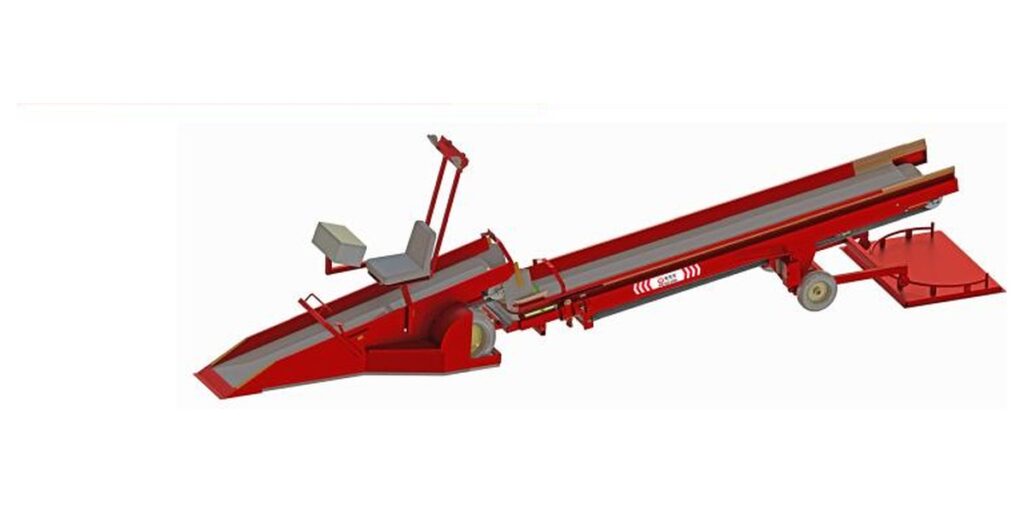
The BCCD-611 bulk storage and retrieval machine is mobile retrieval and transfer equipment, not a structural building silo. Its discharge position can be adjusted without changing the storage line, and a flexible buffer plate reduces impact at the outlet. Those functions support the transfer task, but the site still determines whether the pickup, machine body and outlet can occupy useful positions together. Draw that relationship before selecting a machine by length alone.
Read each length according to its stated definition
The dimensional specifications use different definitions. A conveying length describes a conveying span, while an overall length describes the equipment envelope. Neither automatically gives the horizontal distance between the pile pickup and the receiving point. Inclination, the location of the inlet and outlet, and the space occupied by the machine body affect that relationship. Use the published dimensions for initial screening, then obtain a configuration drawing that identifies the actual transfer points and adjustment positions.
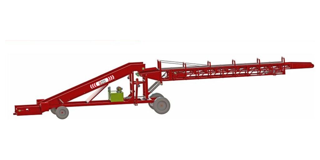
The BDDY-818 bulk stacking and loading machine has a stated overall length range, whereas the BDDE-815 bulk storage and loading machine lists a base length and a length after stretching. Their applications include bulk storage, stacking and loading. These records do not establish identical retrieval functions or comparable effective reach. The comparison below retains each dimensional definition so that a longer number does not become an unsupported layout conclusion.
| Model | Published dimensions | Published capacity | Meaning of the dimensional statement |
|---|---|---|---|
| BCCD-611 | 8000 × 1450 × 1650 mm; conveying length after contraction 7900 mm, after extension 11000 mm | Approximately 60 t/h | The specification distinguishes overall dimensions from contracted and extended conveying lengths. |
| BDDY-818 | Length 17500-22600 mm × width 2500 mm × height 3110 mm | Approximately 80 t/h | The specification states an overall length range together with width and height. |
| BDDE-815 | 10100 × 2850 × 1650 mm; length after stretching 15800 mm | 60 t/h | The specification gives dimensions and a separate length after stretching. |
Check horizontal reach and discharge height separately
Prepare a plan view showing the pile boundary, fixed receiver, columns, walls and door openings. Mark the proposed machine positions and the path used to move between them. For each position, identify where the pickup meets the crop and where the outlet must sit over the receiver. A connection that works only when the machine crosses a required access route is a layout conflict, even if both transfer points fall within the apparent length range.
Then draw an elevation through the transfer. Show floor levels, the receiving opening, overhead obstructions and the intended outlet position. For a given conveying span, increasing inclination reduces its horizontal projection; however, allowable inclination and operating discharge height must come from the proposed configuration. The listed overall height does not establish either value. Check the crop trajectory into the receiver as well, because reaching its edge is insufficient if potatoes overshoot or strike an obstructing lip.
Reserve space for movement, access and restricted traffic
The working envelope includes more than the stationary footprint. It must accommodate permitted extension, rotation, repositioning, operator access and maintenance access. The retrieval machine has a stated rotation angle of 120°, but that angle alone does not define the area swept by the equipment. The pivot location and dimensions of the moving assembly are needed to plot the sweep. Similarly, a distributor swing angle describes that component’s movement rather than a turning circle for the entire machine.
Overlay the working envelope on vehicle and pedestrian routes. Identify which routes remain available during conveying and which require restricted use during repositioning. Include the planned cable route and the space needed to inspect the outlet without entering the crop stream. Avoid selecting arbitrary clearance margins: agree access needs from the equipment arrangement and site procedures. The bulk potato handling solutions review should resolve these interfaces before a machine position becomes a permanent warehouse constraint.
Choose the process role before choosing the longest machine
Define what supplies potatoes to the conveying inlet. A storage retrieval task, a stacking task and loading from an established feed point impose different requirements. The lifting section of the larger stacking option uses a harvesting chain to filter impurities, and that machine supports manual remote control or control-box operation. The compact stacking option combines electric and hydraulic drive and has a fabric distributor that can swing through 180 degrees. These are distinct configuration considerations, not evidence that either machine performs every outloading task.
For a hypothetical store with a fixed receiver beside a doorway, a useful arrangement might keep the outlet aligned while repositioning the pickup as the pile retreats. In another hypothetical store, the receiving point may move with the operation. Compare those arrangements against the intended application and the actual feed interface. The guide to bulk potato storage and stacking flow provides context for separating storage placement from subsequent retrieval when defining the process.
Match the discharge to the receiver's usable rate
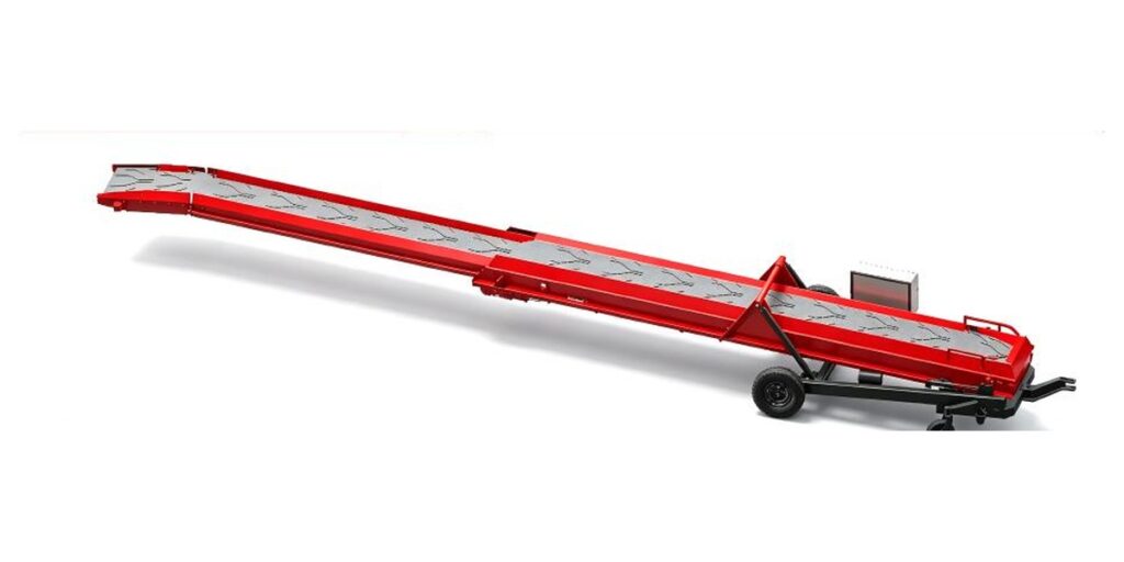
A published machine capacity does not establish sustained warehouse outloading performance. The receiving equipment may accept less material, pause between loads or become unevenly filled. During a pause, continued delivery can create accumulation at the transfer even though the upstream machine remains within its stated capacity. Define how feed will be reduced or stopped when the receiver cannot accept potatoes, and account for material already travelling toward the outlet. Do not assume automatic coordination from the listed controls.
Check the transfer at several working positions, because extension or repositioning can change alignment and the free fall into the receiver. Observe where potatoes first contact the receiving surface, whether the stream stays contained and whether material builds up beneath the outlet. The flexible buffer plate is a stated outlet feature of the retrieval equipment, but it does not establish a universal damage threshold. Representative crop trials are needed to assess the complete transfer under the proposed operating conditions.
Accept the arrangement across its intended working positions
Begin commissioning with an empty movement check following the applicable operating instructions. Exercise the intended positions and verify clearances against the surveyed plan and elevation. Then introduce representative potatoes at a controlled feed and test the initial pile position, an intermediate position and the furthest planned retrieval position. Record machine position, extension, receiver condition and any repositioning required. A successful first discharge proves only that particular arrangement; it does not demonstrate coverage of the storage area.
Agree acceptance criteria before the crop trial. Useful measures include delivered mass over a timed interval, transfer losses, interruptions and visible crop condition before and after handling. Record crop size range, soil condition, sampling method and trial duration so results remain interpretable. Where visible damage is assessed, define the observation method and timing rather than treating a quick visual check as proof of all damage outcomes. Include a representative receiving pause to evaluate the planned stop and restart procedure.
| Trial condition | Observe and record | Likely issue to investigate | Decision |
|---|---|---|---|
| Initial and furthest planned pickup positions | Pickup location, outlet alignment and machine position | Insufficient usable reach or an unsuitable working sequence | Revise positions or receiving location before accepting storage-area coverage. |
| Repositioning beside a column or doorway | Equipment sweep, access route and overhead clearance | Movement envelope conflicts with the building or traffic | Change the route or operating position and repeat the movement check. |
| Representative feed into the receiver | Stream landing point, spill and outlet accumulation | Transfer misalignment or receiving-rate mismatch | Adjust the transfer arrangement or agreed feed before repeating the trial. |
| Receiving pause and restart | Material remaining in transit and accumulation during the pause | Stop sequence does not account for material already moving | Revise the operating sequence and verify restart under the same condition. |
| Crop samples before and after transfer | Sample condition using the agreed observation method and timing | Contact or free fall at the transfer may require adjustment | Revise the transfer and compare equivalent samples in a repeat trial. |
Record the usable envelope and its limits
Turn the accepted trial positions into an operating drawing. Mark where the machine may stand, the transfer points it can serve and the access routes associated with each position. Record any position that requires the receiver to move or the machine to be repositioned. This drawing is more useful than a single maximum-length label because it connects dimensional capability to the warehouse task. Keep the conditions attached to the result, including crop characteristics and the receiving arrangement used during acceptance.
If a far pile position cannot connect to the receiver within the permitted envelope, revise the arrangement: relocate the receiving point, change the working sequence or select equipment suited to that interface. Increasing extension cannot resolve every obstruction or elevation mismatch. Reassess the layout when pile boundaries, traffic routes or receiving requirements change. The practical limit is the set of positions that provide a workable pickup, a contained discharge and the required access under the agreed operating conditions.
Review your warehouse outloading envelope
Send us a dimensioned warehouse plan and elevation, pile boundaries, column and doorway positions, receiving inlet location and height, traffic routes, target hourly delivery, receiving pauses, available electrical supply and representative crop samples or sample details. Include potato size range, soil condition and your proposed acceptance criteria so we can review the outloading reach, clearance and transfer requirements.
- BCCD-611: conveying length after contraction 7900 mm, after extension 11000 mm; rotation angle 120°.
- BDDY-818: Length 17500-22600 mm × width 2500 mm × height 3110 mm; capacity Approximately 80 t/h.
- BDDE-815: 10100 × 2850 × 1650 mm; length after stretching 15800 mm; capacity 60 t/h.
Frequently asked questions
Can I use the published extended length as the distance from the pile to the receiver?
Use it as an initial dimensional reference. The specifications distinguish conveying length, overall length and length after stretching. Usable horizontal connection also depends on inclination, inlet and outlet locations, machine position and obstructions. A configuration drawing should establish whether the actual pickup and discharge points connect throughout the planned outloading sequence.
Is the potato silo machine a permanent storage structure?
The equipment discussed here is mobile bulk potato retrieval and transfer equipment, rather than a structural building silo. Its stated applications include bulk storage, retrieval and transfer. Warehouse design must still provide the storage space and a workable relationship between the changing pile, equipment positions and receiving point.
How much turning clearance should we leave around the machine?
The equipment specifications do not establish a universal clearance distance. Plot the equipment sweep using the proposed configuration, pivot location and moving assembly dimensions, then add the access required by the site arrangement. A rotation angle or distributor swing angle alone cannot establish the turning envelope of the whole machine.
Will the listed capacity be achieved throughout an outloading shift?
The listed capacity is a machine specification, not an acceptance result for your warehouse. Actual delivery depends on feed availability, receiving rate, pauses and repositioning. Agree a timed delivery trial using representative potatoes and planned working positions, and record interruptions alongside delivered mass so the result reflects the intended operating sequence.
What should an outloading acceptance trial include?
Check empty movement first, then run representative potatoes from initial, intermediate and furthest planned pickup positions. Record discharge alignment, timed delivery, transfer losses and crop observations using an agreed sampling method. Include a receiving pause and restart, and retain the machine positions and crop conditions with the acceptance record.
Engineering note
Project drawings should establish transfer-point locations, permitted adjustment positions and access requirements for the proposed configuration. Acceptance should document representative crop conditions, receiving behavior and the working positions actually tested.
 English
 Chinese
 Spanish
 German
 French
 Russian
 Urdu
 Bengali
 Kazakh
 Ukrainian
 Dutch
 Polish